n expanding mall recognized that their shortage of parking spaces was going to become a limiting factor in their future development. They decided to renovate and build an addition onto the existing parking garage, providing the structure was sound and would support the planned addition.
Challenges
The mall had changed owners a number of times and no as-built drawing existed that detailed the construction of the old structure. One of the key points of interest was the position of post tension (PT) cables throughout the levels.
Post–tension cables are used in concrete construction to allow thinner slabs and greater span lengths between support columns. These cables, composed of steel wires inserted into a plastic sheath, are subsequently "tensioned" and grouted after the concrete is poured.
The engineering company hired also recognized that the contractors who would eventually be hired to do the renovation would have to avoid cutting any of the cables. The tremendous tension in the cable makes cutting it dangerous for the operator and compromises the structure's integrity.
Solution
Sample areas of interest were chosen to be scanned with Conquest® 100 ground penetrating radar (GPR) so the internal structure of the parking garage could be determined. Conquest’s flexibility allowed the scanners to collect grids over large and small areas quickly. In addition the Conquest’s 1000 MHz antenna provided the penetrating power to see deep into the slab and find all structural components.
The unique aspects of post-tension cables allows GPR imaging to identify these features with a high level of certainty.
- The cables are normally below the top layer of rebar.
- The cables are often bundled together in a grouping
- The cables droop lower in the slab between support columns
Results & benefits
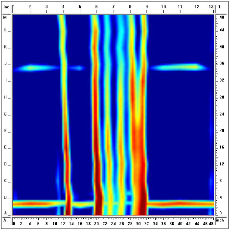
The areas scanned on the old parking garage provided a clear answer. Post-tension cables were present throughout the structure. This is clearly shown in the depth slice image(Figure 1). The red vertical lines show the PT cables bundled together at a tight spacing.

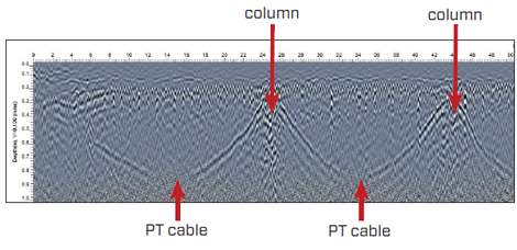
In addition lines were run directly over and parallel to the post-tension cables to observe their position in the slab. The grey scale image (Figure 2) shows the cables descending into the slab and then rising up as they near the columns.

Knowing that the post-tension cables were installed properly and there were a sufficient number of them was a strong indicator to the mall management that they could move forward and solve their parking problem.
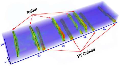
The EKKO_Project™ GPR software also allows data to be exported to 3D picture (Figure 3).

Overall this case study shows some key benefits of GPR:
- Grid imaging is key to seeing the unique attributes of PT cables.
- Real-time depth imaging is essential for cost-effective site evaluation.
- Conquest provides compact, portable easy-to-use on-site imaging capability.
- Imaging over large areas allows for trends to be recognized and important structural components to be identified.
Download the case study: Post-Tension Cable Characteristics
Learn more about Conquest® GPR


